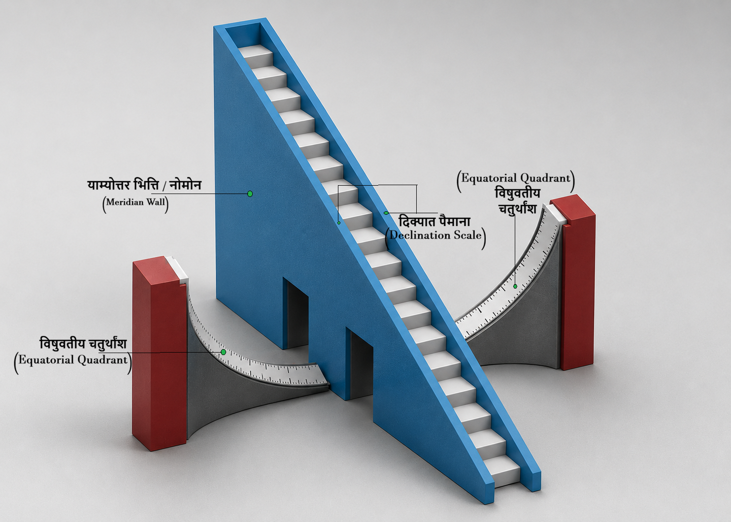
The working principle of the Samrāṭ Yantra is based on the geocentric model, in which the apparent motion of the Sun is observed with the Earth considered as the reference frame. As seen from the Earth, the Sun appears to move along the Ecliptic throughout the year. On any given day, its apparent daily motion may be regarded as a circular path about the Earth's rotational axis. Since the Earth completes one rotation in approximately 24 hours, the Sun appears to move at an angular rate of 15° per hour (360° ÷ 24), completing an apparent revolution of 360° around the Earth's axis every day.
The hypotenuse of the Samrāṭ Yantra is aligned parallel to the Earth's rotational axis. Consequently, as the Earth rotates, the shadow cast by the Meridian Wall (Gnomon) moves uniformly across the Equatorial Quadrants at the same angular rate of 15° per hour, allowing the direct measurement of Local Solar Time.
At sunrise, the Sun's rays are nearly parallel to the horizon, causing the shadow of the Meridian Wall to fall on the Western Equatorial Quadrant. The tip of the shadow appears near the upper end of the quadrant, corresponding to approximately 6:00 AM Local Solar Time. As the Sun rises higher in the sky, the shadow tip moves progressively downward across the western quadrant at a uniform rate of 15° per hour.
At Local Solar Noon, the Sun lies in the Meridian Plane. At this instant, the shadow of the Meridian Wall does not fall on either equatorial quadrant, and the time corresponds to the lowest graduation of the instrument.
After noon, as the Sun moves west of the meridian, the shadow begins to fall on the Eastern Equatorial Quadrant. The shadow tip then advances steadily across the eastern quadrant as the Sun continues its apparent westward motion. By sunset, the shadow reaches the upper end of the eastern quadrant, indicating approximately 6:00 PM Local Solar Time.
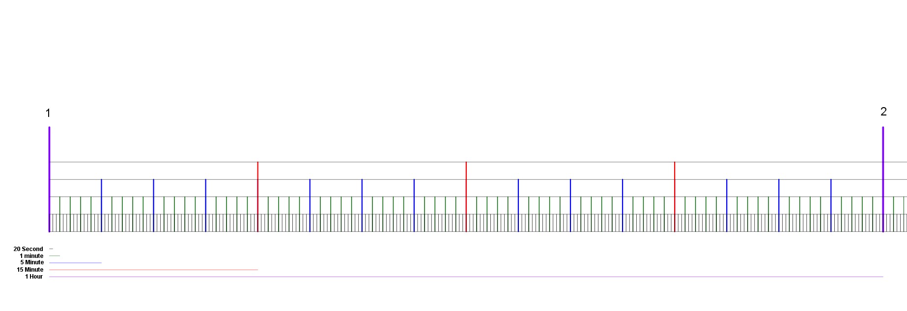
Thus, the position of the shadow on the equatorial quadrants enables highly precise determination of Local Solar Time. Standard Time is obtained by applying the appropriate Standard Time Correction to the Local Solar Time, either by adding or subtracting the required correction.
Use the annual correction table given below to apply the required correction (in minutes) to the Local Solar Time and obtain the corresponding Standard Time.
| Date | Min |
|---|
| JAN |
| 01 | 30 |
| 02 | 31 |
| 04 | 32 |
| 07 | 33 |
| 09 | 34 |
| 11 | 35 |
| 14 | 36 |
| 17 | 37 |
| 20 | 38 |
| 23 | 39 |
| 27 | 40 |
| FEB |
| 01 | 41 |
| 25 | 40 |
| MAR |
| 03 | 39 |
| 07 | 38 |
| 11 | 37 |
| 15 | 36 |
| 19 | 35 |
| 22 | 34 |
| 25 | 33 |
| 29 | 32 |
| APR |
| 01 | 31 |
| 04 | 30 |
| 08 | 29 |
| 11 | 28 |
| 15 | 27 |
| 19 | 26 |
| 24 | 25 |
| 29 | 24 |
| MAY |
| 08 | 23 |
| 24 | 24 |
| Date | Min |
|---|
| JUN |
| 02 | 25 |
| 07 | 26 |
| 13 | 27 |
| 18 | 28 |
| 23 | 29 |
| 27 | 30 |
| JUL |
| 02 | 31 |
| 07 | 32 |
| 14 | 33 |
| AUG |
| 10 | 32 |
| 16 | 31 |
| 20 | 30 |
| 25 | 29 |
| 29 | 28 |
| SEP |
| 01 | 27 |
| 04 | 26 |
| 07 | 25 |
| 10 | 24 |
| 13 | 23 |
| 16 | 22 |
| 19 | 21 |
| 22 | 20 |
| 24 | 19 |
| 27 | 18 |
| 30 | 17 |
| Date | Min |
|---|
| OCT |
| 03 | 16 |
| 07 | 15 |
| 10 | 14 |
| 14 | 13 |
| 18 | 12 |
| 24 | 11 |
| NOV |
| 16 | 12 |
| 21 | 13 |
| 25 | 14 |
| 28 | 15 |
| DEC |
| 01 | 16 |
| 04 | 17 |
| 06 | 18 |
| 09 | 19 |
| 11 | 20 |
| 13 | 21 |
| 15 | 22 |
| 17 | 23 |
| 19 | 24 |
| 21 | 25 |
| 23 | 26 |
| 25 | 27 |
| 27 | 28 |
| 29 | 29 |
Hour Angle
The Hour Angle (H) of the Sun can be determined from the Local Solar Time (LST) using the following relation:
H = (LST − 12) × 15°
Where:
- H = Hour Angle of the Sun
- LST = Local Solar Time (in hours)
Example:
If the Local Solar Time is 14:30 (i.e., 14.5 hours),
H = (14.5 − 12) × 15° = 37.5°
Therefore, the Sun is located 37.5° west of the local meridian.
Solar Declination
Measurement of Declination
The Samrāṭ Yantra can be used to determine the declination of a celestial object, particularly the Sun. For this purpose, the Meridian Wall (Yāmyottara Bhitti) serves as the primary measuring element.
Direct Measurement
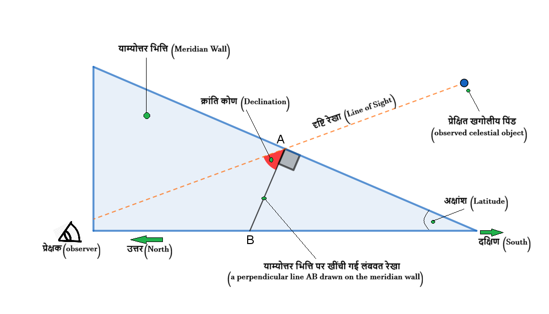
To determine the declination of a celestial object by direct observation, consider a line AB drawn perpendicular to the meridian wall through the midpoint of its hypotenuse. This line serves as the reference line for measuring declination.
When the observed celestial object crosses the Meridian Plane, both the object and the meridian wall lie in the same vertical plane. At this instant, the observer aligns their line of sight so that the reference point on the meridian wall and the celestial object appear along the same straight line.
In practice, this alignment may be achieved using a rope attached to the reference point on the meridian wall. The observer adjusts the rope until it coincides with the line of sight toward the celestial object. The angle between the rope (line of sight) and the perpendicular reference line AB represents the declination angle of the celestial object.
Since the hypotenuse of the meridian wall is inclined to the horizontal by an angle equal to the latitude of the observing location, the perpendicular line AB represents the direction of 0° declination (the Celestial Equator). Any celestial object lying along this line therefore has zero declination.
-
If the observed object lies south of line AB, its declination is negative (−), indicating that it is located in the Southern Celestial Hemisphere.
-
If the observed object lies north of line AB, its declination is positive (+), indicating that it is located in the Northern Celestial Hemisphere.
Indirect Measurement of Declination
Direct Measurement
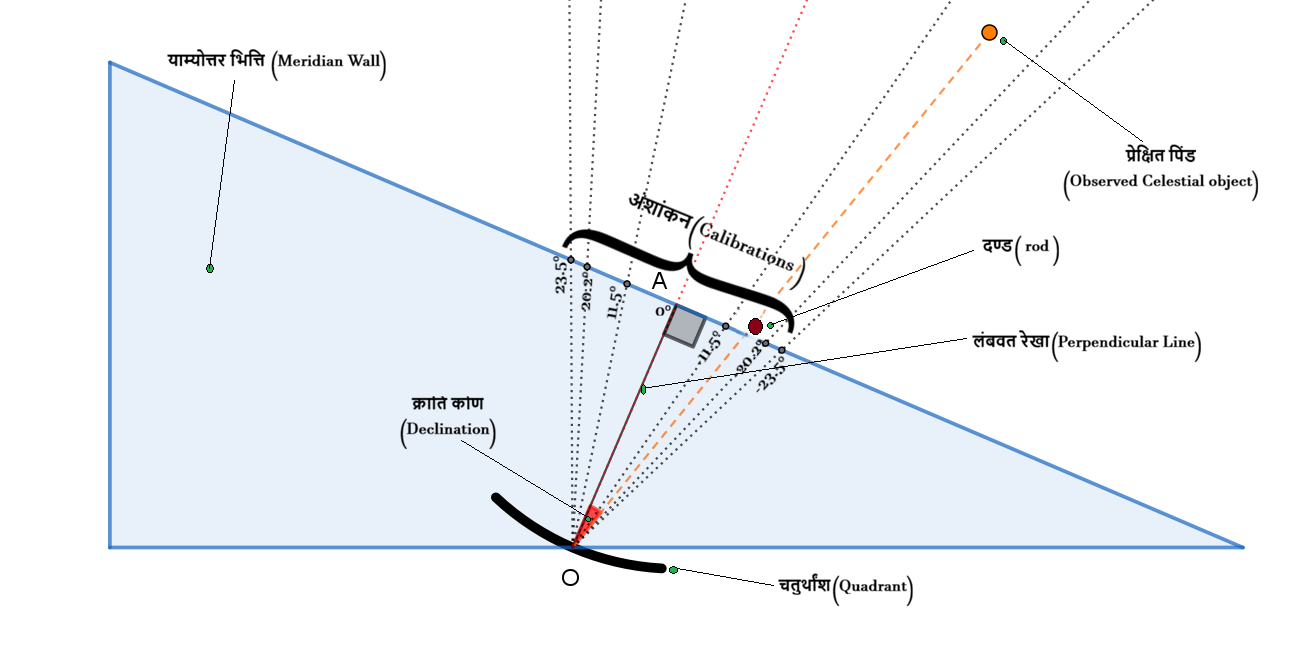
The declination of the Sun can also be determined indirectly by observing the shadow cast on the equatorial quadrant. For this purpose, a short rod is mounted on the hypotenuse of the Meridian Wall (Yāmyottara Bhitti) so that it remains perpendicular to the meridian plane.
When the Sun lies on the Celestial Equator (0° declination), the rod is positioned at a specific point on the hypotenuse such that its shadow falls exactly at the centre of the corresponding quadrant. This point, denoted by A, serves as the reference position for 0° declination.
Taking the lowest point of the quadrant, denoted by O, as the centre of the graduated arc, angular markings are made on the hypotenuse with respect to the reference line OA. The graduations above A represent positive (northern) declinations, while those below represent negative (southern) declinations.
To determine the Sun's declination on any day of the year, the rod is moved along the hypotenuse of the meridian wall while keeping it perpendicular to the meridian plane, until its shadow once again falls at the centre of the quadrant.
The position of the rod on the hypotenuse then coincides with one of the calibrated angular graduations. The corresponding reading gives the declination angle of the Sun directly.
Measurement of Right Ascension (RA)
The Right Ascension (RA) of an unknown celestial object can be determined by comparing its Hour Angle with that of a reference star whose Right Ascension is already known.
First, measure the Hour Angle of both the reference star and the target object using the Samrāṭ Yantra. Let the difference between their Hour Angles be α.
If the reference star lies east of the target object, the Right Ascension of the object is obtained by subtracting α from the known Right Ascension of the reference star. Conversely, if the reference star lies west of the target object, α is added to the reference star's Right Ascension.
RAobject = RAreference ± α
To measure the Hour Angle, the observer moves along the equatorial quadrant until the target object (or reference star) and the 0° mark on the inclined meridian wall appear aligned along the same line of sight. The observer's position on the graduated quadrant then provides the Hour Angle, which may also be calculated using the relation:
H = (LST − 12) × 15°
Once the Hour Angles of both objects are known, their difference (α) is used with the known Right Ascension of the reference star to determine the Right Ascension of the target object.